


Description
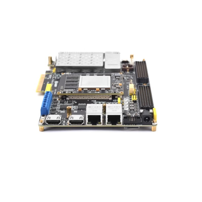
The resources of the development board baseboard are as follows:
- 1 core board interface, compatible with PunkAtom KU-040/KU-060 core boards
- Four optical fiber interfaces
- 1 QSFP interface
- Two FMC HPC connectors
- 1 PCIe 3.0 X8 interface
- 1 OLED/Camera module interface
- 2 RS485 interfaces
- 2 CAN interfaces
- 1 reset button, which can serve as a reset signal for FPGA program execution
- 2 function buttons
- 2 status indicators (LED1~LED2: red)
- 1 power indicator (blue)
- Two HDMI interfaces (one input, one output)
- 1 TF card slot (on the back of the baseboard)
- 1 XADC interface
- Two Gigabit Ethernet interfaces
- 1 JTAG debug/download port (10-pin)
- 1 OLED interface
- 1 set of BANK voltage switching interfaces
- EEPROM chip: AT24C64, Capacity: 64Kbit (8KB)
- 1 ATK module interface, compatible with ALIENTEK Bluetooth/GPS/MPU6050/RGB light modules
- 1 standard LVDS TFT-LCD interface; can connect to RGB LCDs via the LVDS2RGB module (ATK_MO8284)
- 1 USB to UART interface
- 1 FAN interface
- 1 set of 5V power expansion ports (supports output and external input)
- 1 set of 3.3V power expansion ports (supports output and external input)
- 1 DC power input interface (Input voltage range: DC 6~16V)
- 1 RTC backup battery holder (with battery included)
- 1 RTC real-time clock (using PCF8563 chip)
- 1 power switch (controls the entire board's power)
The KU core board is rich in onboard resources and can meet the requirements of various applications. The core board has a compact form factor measuring 72mm x 60mm and utilizes surface-mount board-to-board connectors. It features four 168-pin high-speed connector seats labeled CN1 to CN4. The number of pins led out from each connector is 132, 127, 123, and 118 respectively, totaling 500 pins via the board-to-board connectors.
The KU060 can utilize all 500 pins, while the KU040 can use 460 pins, making it highly adaptable for various projects.
The KU-040 and KU-060 core boards are identical in terms of peripheral components, with the only difference being the main FPGA chip. The specific resources are as follows:
- The main FPGA chip uses the Xilinx Kintex UltraScale series.
- The KU-040 core board uses the XCKU040-FFVA1156-2I FPGA, featuring up to 530K logic cells, 21.1Mbit of BRAM, and 20 GTH transceivers.
- The KU-060 core board uses the XCKU060-FFVA1156-2I FPGA, featuring up to 725K logic cells, 38Mbit of BRAM, and 28 GTH transceivers.
- 4 DDR4 SDRAM chips, model MT40A512M16, each with 8Gbit capacity, totaling 32Gbit (4GB).
- 2 QSPI FLASH chips, model N25Q128, each with a capacity of 128Mbit (16MB).
- 1 Crystal Oscillator: 100MHz, located on the back of the core board, providing a differential clock to the FPGA.
- 1 Power Indicator.
- 1 Configuration Done Indicator (DONE LED).