
Description
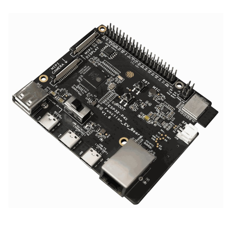
ESP32-P4X-Function-EV-Board is a multimedia development board based on the ESP32-P4 chip. ESP32-P4 chip features a dual-core RISC-V processor and supports up to 32 MB PSRAM. In addition, ESP32-P4 supports USB 2.0 specification, MIPI-CSI/DSI, H264 Encoder, and various other peripherals. With all of its outstanding features, the board is an ideal choice for developing low-cost, high-performance, low-power network-connected audio and video products.
The 2.4 GHz Wi-Fi 6 & Bluetooth 5 (LE) module ESP32-C6-MINI-1 serves as the Wi-Fi and Bluetooth module of the board. The board also includes a 7-inch capacitive touch screen with a resolution of 1024 x 600 and a 2MP camera with MIPI CSI, enriching the user interaction experience. The development board is suitable for prototyping a wide range of products, including visual doorbells, network cameras, smart home central control screens, LCD electronic price tags, two-wheel vehicle dashboards, etc.


|
No. |
Key Component |
Description |
|---|---|---|
|
1 |
J1 |
All available GPIO pins are broken out to the header block J1 for easy interfacing. For more details, see Header Block. |
|
2 |
ESP32-C6 Module Programming Connector |
The connector can be used with ESP-Prog or other UART tools to flash firmware onto the ESP32-C6 module. |
|
3 |
ESP32-C6-MINI-1 Module |
This module serves as the Wi-Fi and Bluetooth communication module for the board. |
|
4 |
Microphone |
Onboard microphone connected to the interface of Audio Codec Chip. |
|
5 |
Reset Button |
Resets the board. |
|
6 |
Audio Codec Chip |
ES8311 is a low-power mono audio codec chip. It includes a single-channel ADC, a single-channel DAC, a low-noise pre-amplifier, a headphone driver, digital sound effects, analog mixing, and gain functions. It interfaces with the ESP32-P4 chip over I2S and I2C buses to provide hardware audio processing independent of the audio application. |
|
7 |
Speaker Output Port |
This port is used to connect a speaker. The maximum output power can drive a 4 Ω, 3 W speaker. The pin spacing is 2.00 mm (0.08”). |
|
8 |
Audio PA Chip |
NS4150B is an EMI-compliant, 3 W mono Class D audio power amplifier that amplifies audio signals from the audio codec chip to drive speakers. |
|
9 |
5 V to 3.3 V LDO |
A power regulator that converts a 5 V supply to a 3.3 V output. |
|
10 |
BOOT Button |
The boot mode control button. Press the Reset Button while holding down the Boot Button to reset ESP32-P4 and enter firmware download mode. Firmware can then be downloaded to SPI flash via the USB-to-UART Port. |
|
11 |
Ethernet PHY IC |
Ethernet PHY chip connected to the ESP32-P4 EMAC RMII interface and RJ45 Ethernet Port. |
|
12 |
Buck Converter |
A buck DC-DC converter for the 3.3 V power supply. |
|
13 |
5 V Power-on LED |
This LED lights up when the board is powered through any USB Type-C port. |
|
14 |
RJ45 Ethernet Port |
An Ethernet Port supporting 10/100 Mbps adaptive. |
|
No. |
Key Component |
Description |
|---|---|---|
|
15 |
USB Full-speed Port |
USB Type-C port that supports USB 2.0 Full-speed data rate. It can be used as the power supply interface for the development board and as a communication interface. |
|
16 |
USB Serial/JTAG Port |
USB Type-C port that supports USB 2.0 Full-speed data rate. It can be used to flash firmware to the ESP32-P4 chip, communicate with the chip via the USB protocol, and perform JTAG debugging. |
|
17 |
USB 2.0 Type-C Port |
The USB 2.0 Type-C Port is connected to the USB 2.0 OTG High-Speed interface of ESP32-P4, compliant with the USB 2.0 specification. When communicating with other devices via this port, ESP32-P4 acts as a USB device connecting to a USB host. Please note that USB 2.0 Type-C Port and USB 2.0 Type-A Port cannot be used simultaneously. USB 2.0 Type-C Port can also be used for powering the board. |
|
18 |
USB 2.0 Type-A Port |
The USB 2.0 Type-A Port is connected to the USB 2.0 OTG High-Speed interface of ESP32-P4, compliant with the USB 2.0 specification. When communicating with other devices via this port, ESP32-P4 acts as a USB host, providing up to 500 mA of current. Please note that USB 2.0 Type-C Port and USB 2.0 Type-A Port cannot be used simultaneously. |
|
19 |
Power Switch |
Power On/Off Switch. Toggling toward the ON sign powers the board on (5 V), toggling away from the ON sign powers the board off. |
|
20 |
Switch |
TPS2051C is a USB power switch that provides a 500 mA output current limit. |
|
21 |
MIPI CSI Connector |
The FPC connector 1.0K-GT-15PB is used for connecting external camera modules to enable image transmission. For details, please refer to 1.0K-GT-15PB specification in Related Documents. FPC specifications: 1.0 mm pitch, 0.7 mm pin width, 0.3 mm thickness, 15 pins. |
|
22 |
Buck Converter |
A buck DC-DC converter for VDD_HP power supply of ESP32-P4. |
|
23 |
ESP32-P4 |
A high-performance MCU with large internal memory and powerful image and voice processing capabilities. |
|
24 |
40 MHz XTAL |
An external precision 40 MHz crystal oscillator that serves as a clock for the system. |
|
25 |
32.768 kHz XTAL |
An external precision 32.768 kHz crystal oscillator that serves as a low-power clock while the chip is in deep-sleep mode. |
|
26 |
MIPI DSI Connector |
The FPC connector 1.0K-GT-15PB is used for connecting displays. For details, please refer to 1.0K-GT-15PB Specification in Related Documents. FPC specifications: 1.0 mm pitch, 0.7 mm pin width, 0.3 mm thickness, 15 pins. |
|
27 |
SPI flash |
The 16 MB flash is connected to the chip via the SPI interface. |
|
28 |
MicroSD Card Slot |
The development board supports a MicroSD card in 4-bit mode and can store or play audio files from the MicroSD card. |
Documentation
- ESP32-P4X-Function-EV-Board Reference Design (ZIP)
- ESP32-P4 Series SoC Errata
- 1.0K-GT-15PB Specification (PDF)
- Camera Datasheet (PDF)
- Display Datasheet (PDF)
- Datasheet of display driver chip EK73217BCGA (PDF)
- Datasheet of display driver chip EK79007AD (PDF)
- LCD Adapter Board Schematic (PDF)
- LCD Adapter Board PCB Layout (PDF)
- Camera Adapter Board Schematic (PDF)
- Camera Adapter Board PCB Layout (PDF)