


Alientek
STM32F429IGT6 apollo development board
STM32F429IGT6 apollo development board
SKU:E02015-001
• Shipping cost $5 within AU, more details
• Shipping to Non-Australia, contact us
• Accept 30-day returns, see details.
In stock
Couldn't load pickup availability
View full details


Product Overview
Hardware Design Features of the Apollo V2 Base Board:
1. Abundant Interfaces
The board offers over ten types of standard interfaces, facilitating convenient experimentation and development with various peripherals.
2. Flexible Design
- Adopting a core board + carrier board structure, one carrier board supports multiple MCUs, reducing redundant investments.
- Most onboard resources are flexibly configurable to adapt to different usage scenarios.
- 110 I/O pins are exposed, greatly simplifying expansion and usage.
- The one-click download feature eliminates the hassle of repeatedly setting BO and B1, enabling STM32 development with just a single USB cable.
3. Comprehensive Resources
The board integrates a high-performance audio codec, a six-axis sensor, a magnetometer, a 100M Ethernet controller, an ambient light sensor, and various interface chips to meet diverse application requirements.
4. User-Friendly Design
- All interfaces are clearly labeled with silkscreen markings and outlined for intuitive use.
- Frequently used peripherals are highlighted with large silkscreen labels for easy identification.
- Interfaces are ergonomically positioned for convenient access.
- Resources are logically allocated to ensure optimal utilization.
Apollo V2 Base Board Specifications
Core Board Interface
- 1× Core board interface for STM32F429/F767/H743
Indicators & Controls
- 1× Blue power indicator
- 2× Status indicators: Red (DS0), Green (DS1)
- 1× Reset button for MCU/LCD
- 4× Function buttons: KEY0, KEY1, KEY2, KEY_UP (with wake-up function)
- 1× Capacitive touch button (TPAD)
- 1× Power switch (main board control)
- 1× Adjustable potentiometer (RV1) for ADC testing
Audio Components
- 1× Active buzzer
- 1× Onboard speaker (backside)
- 1× Audio codec chip (ES8388)
- 1× Stereo audio output interface
- 1× Stereo recording input interface
- 1× Recording microphone
- 1× Optical input interface (SPDIF audio)
Sensors & Modules
- 1× Ambient light sensor (light intensity, proximity, IR)
- 1× 6-axis sensor (SH3001: gyroscope + accelerometer)
- 1× Magnetometer (ST480MC)
- 1× Digital temperature/humidity sensor interface (DS18B20/DHT11)
- 1× Wireless module interface (NRF24L01 compatible)
- 1× ATK module interface (Bluetooth, GPS, MPU6050, etc.)
Communication Interfaces
- 1× CAN interface (120Ω terminal resistor)
- 1× RS485 interface (120Ω terminal resistor)
- 2× RS232 interfaces (male & female)
- 1× USB to UART
- 1× USB Slave interface
- 1× USB Host interface
- 1× 10M/100M Ethernet port
- 1× TF card interface
Display & Camera
- 1× LCD interface (2.8/3.5/4.3/7-inch TFT LCD)
- 1× Camera module interface (shared with OLED)
- 1× OLED module interface (shared with camera)
Configuration & Debugging
- 1× JTAG/SWD debug interface
- 1× Reference voltage setting interface (ADC)
- 1× Boot mode selection interface
- 1× RS232/485 selection interface
- 1× RS232/Module selection interface
- 1× CAN/USB selection interface
- 1× Multi-function interface (DAC/ADC/PWM/AUDIO IN/TPAD)
Power Management
- 1× DC power input (DC6V-15V, DC005)
- 1× Backup battery interface (RTC)
- 1× 5V power input/output
- 1× 3.3V power input/output
Special Features
- 110× Extended I/O pins
- 1× One-click download circuit (proprietary)
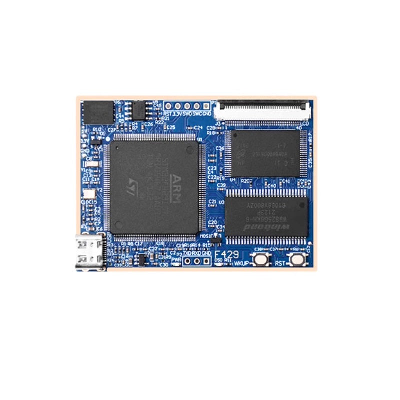
Hardware Design Features of the Apollo V2 Core Board
The Apollo V2 STM32F429 core board incorporates the following key hardware design characteristics:
1. Compact Form Factor
The core board measures just 65mm × 45mm, making it highly suitable for integration into a wide range of projects.
2. Comprehensive Interface Support
The board features built-in interfaces including a serial port, SWD debug interface, RGB LCD interface, USB interface, and 3.3V & 5V power interfaces. Additionally, it provides 110 I/O pins through board-to-board connectors, meeting the requirements of diverse applications.
3. Abundant Onboard Resources
Equipped with substantial memory resources, the core board includes 32MB SDRAM, 32MB SPI FLASH, 512MB NAND FLASH, and EEPROM, ensuring it can handle various application demands effectively.
Apollo V2 STM32F429 Core Board Specifications
Main Controller
- CPU: 1 × STM32F429IGT6
- Flash: 1024KB
- SRAM: 256KB
Memory & Storage
- SDRAM: 1 × W9825G6KH (32MB)
- NAND Flash: 1 × 512MB
- SPI Flash: 1 × 32MB
- EEPROM: 1 × 24C02 (256B)
Indicators & Controls
- Power Indicator: 1 × Blue LED
- Status Indicator: 1 × Red LED (DS0)
- Reset Button: 1 × For MCU/LCD reset
- Function Button: 1 × WK_UP (with MCU wake-up capability)
Communication & Debug Interfaces
- TTL Serial Port: 1 × USART1 (for communication/debugging)
- SWD Debug Interface: 1 × For code download and emulation
- Type-C USB: 1 × For USB communication and board power supply
Power & Expansion
- Power Points: 1 × 5V & 3.3V pads (external power input/output)
- RGB LCD Interface: 1 × Supports RGB565 displays
- Board-to-Board Connectors: 2 × Bottom-mounted, exposing 110 I/O pins for carrier board compatibility