


Alientek
STM32F767IGT6 apollo development board
STM32F767IGT6 apollo development board
SKU:E02016-001
• Shipping cost $5 within AU, more details
• Shipping to Non-Australia, contact us
• Accept 30-day returns, see details.
In stock
Couldn't load pickup availability
View full details


Product Overview
The Apollo development board adopts a core board + carrier board design. The following section introduces the design features of the Apollo V2 STM32F767 carrier board. The board provides over ten standard interfaces, enabling convenient experimentation and development with various peripherals.
Many resources on the board can be flexibly configured to meet different usage conditions. With 110 I/O pins exposed, it greatly facilitates user expansion and application. The onboard one-click download function eliminates the need for frequent B0 and B1 settings, allowing STM32 development with just a single USB cable.
The board features a high-performance audio codec, a six-axis sensor, a magnetometer, a Gigabit Ethernet controller, an ambient light sensor, and various interface chips to meet diverse application requirements.
Core Board Interface
- 1 port for connecting STM32F429/F767/H743 core boards
Indicators
- 1 blue power indicator
- 2 status indicators: red (DS0), green (DS1)
Buttons
- 1 reset button for MCU/LCD
- 4 function buttons: KEY0, KEY1, KEY2, KEY_UP (with wake-up function)
- 1 capacitive touch button (TPAD)
Power Management
- 1 power switch for board control
- 1 adjustable potentiometer (RV1) for ADC testing
- DC power input interface (DC6V-15V, DC005 connector)
- Backup battery interface for RTC
- 5V power input/output port
- 3.3V power input/output port
Audio Components
- 1 active buzzer
- 1 onboard speaker (on board backside)
- 1 audio codec chip (ES8388)
- 1 stereo audio output interface
- 1 stereo recording input interface
- 1 recording microphone (MIC)
- 1 optical input interface for SPDIF audio signals
Sensors
- 1 ambient light sensor (measures light intensity, proximity, IR intensity)
- 1 six-axis sensor (SH3001: 3-axis gyroscope + 3-axis accelerometer)
- 1 magnetometer (ST480MC)
- 1 digital temperature/humidity sensor interface (supports DS18B20, DHT11, etc.)
Communication Interfaces
- 1 CAN interface (with 120Ω terminal resistor)
- 1 RS485 interface (with 120Ω terminal resistor)
- 2 RS232 interfaces (male and female)
- 1 USB to UART interface
- 1 USB Slave interface
- 1 USB Host interface
- 10M/100M Ethernet port
Expansion & Debugging
- 1 JTAG/SWD debug port
- 1 TF card interface
- 1 wireless module interface (supports NRF24L01, etc.)
- 1 ATK module interface (supports various modules: Bluetooth, GPS, MPU6050, etc.)
- 1 LCD interface (supports 2.8/3.5/4.3/7-inch TFT LCD modules)
- 1 camera module interface (shared with OLED)
- 1 OLED module interface (shared with camera)
- 110 extended I/O pins
Configuration Interfaces
- 1 reference voltage setting interface for ADC
- 1 boot mode selection interface
- 1 RS232/485 selection interface
- 1 RS232/module selection interface
- 1 CAN/USB selection interface
- 1 multi-function interface group (for DAC/ADC/PWM/AUDIO IN/TPAD, etc.)
- 1 one-click download circuit (proprietary design)
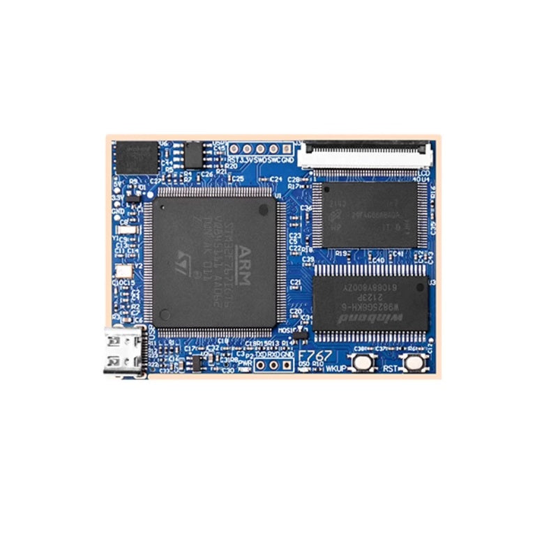
The hardware design of the Apollo V2 STM32F767 core board features the following characteristics: The core board measures only 65mm × 45mm, making it easy to integrate into various projects.
The core board includes serial ports, an SWD debug interface, an RGB LCD interface, a USB interface, and 3.3V & 5V power interfaces. Additionally, it provides 110 I/O pins through board-to-board connectors, meeting the requirements of diverse applications.The core board is equipped with ample storage, including 32MB SDRAM, 32MB SPI FLASH, 512MB NAND FLASH, and EEPROM, ensuring it can handle a wide range of application needs.
Core Board Specifications
Main Controller
- CPU: 1 × STM32F767IGT6
- Flash: 1024KB
- SRAM: 512KB
Memory & Storage
- SDRAM: 1 × W9825G6KH (32MB)
- NAND Flash: 1 × 512MB
- SPI Flash: 1 × 32MB
- EEPROM: 1 × 24C02 (256B)
Indicators & Controls
- Power Indicator: 1 × Blue LED
- Status Indicator: 1 × Red LED (DS0)
- Reset Button: 1 × For MCU/LCD reset
- Function Button: 1 × WK_UP (with MCU wake-up capability)
Communication & Debug Interfaces
- TTL Serial Port: 1 × USART1 (for communication/debugging)
- SWD Debug Interface: 1 × For code download and emulation
- Type-C USB: 1 × For USB communication and board power supply
Power & Expansion
- Power Points: 1 × 5V & 3.3V pads (external power input/output)
- RGB LCD Interface: 1 × Supports RGB565 displays
- Board-to-Board Connectors: 2 × Bottom-mounted, exposing 110 I/O pins for carrier board compatibility